 Jacob Middleton
 Jacob Middleton - St. Francis, MN
| Merlin |

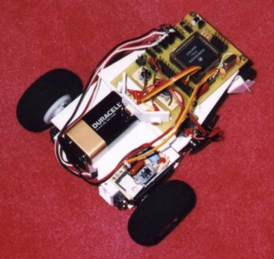
This was a over a year ago around April '97. After researching some more on walking robots, I decided that I was going to try to design and build my own six-legged walking robot, but about two months into the designing process, I realized that I knew basically nothing about actually building or designing robots, especially walking ones! I thought that this might be a problem :-), so I decided to make sure that I could at least design and build a simple robot before I tried to build a walking one. For the "simple" robot I was going to design and build, I decided on a small wheeled one, and so Merlin began.
The first thing I did in making Merlin was go through about half a dozen different robot designs until I found one that I was completely satisfied with. This robot design used two modified servos ( which are in the front ) with two-inch model airplane wheels attached to them for the drive system. This worked pretty well when I actually built Merlin, the only drawback is that servos are not meant to be used as drive motors, and when they are they use a lot of power for continuous rotation, i.e. Merlin's batteries wear out quickly.
The next thing I did in building Merlin was to construct a BotBoard for the micro controller www.rdrop.com/users/marvin. Although the BotBoard was supposed to be one of the easiest micro controllers to use, it proved to be rather difficult for a first time robot builder like myself to get it to work, and in fact I probably would have never gotten it to work properly if Jeff Sampson from the Twin Cities Robotics group had not stepped in and given me invaluable advice on how to construct it and how to get my programs to work.
At about the same time I was building my BotBoard, I was also constructing Merlin's frame out of one-eighth inch plastic. I had already drawn all sides of the frame on graph paper, so when I actually went to build it I knew exactly what to do. Some of the main features of the frame include: two casters in the back, a cubicle built into the frame for enclosing the servo's power supply, cubicles for inclosing the servos, and a head which I later abandoned because it was not necessary. Note that I mention cubicles, what I mean by this is instead of having a flat base that you place electronics on and build a frame on top of, such as most robots, the way I built Merlin was to build the frame around the electronics and other components. I found that this was much more space efficient, allowing me to build a smaller and more stable robot.
Now I installed most of the electronics, such as the two modified servos, the five-volt regulator, and the completed and now working BotBoard. Merlin could now run forward, but he could not sense anything yet. I then started writing programs in Sbasic to try to get him to do simple things like draw a square with his motions on the floor, or sense when a switch was on or off, things that would seem to be easy, but alas, I could not get Merlin to do much with his servos, and I could not get him to sense anything accurately. Seeing that I needed help from someone that knew what he was doing, I started e-mailing Jeff Sampson who again gave me a lot of advice on my BotBoard and my programs. He also sent me web site addresses for first-time robot builders. After following Jeff's advice I got my BotBoard to accurately sense inputs and Merlin's servos to move the way I wanted.
After rigging up two light sensors the day before and cobbling together a program to use them, I brought Merlin to a robot demonstration which was incorporated into the Robot Zoo at the Science Museum. After this, I stopped working on Merlin for three months ( it had now been about eight months since I had started on Merlin ). When I began working on Merlin again, I permanently installed three photo resistors ( instead of two ), and I wrote a better program to enable Merlin to seek out bright light. The photo resistors did not all have the same sensitivity, that is, in the same light they would give different readings. To solve this problem I installed a variable resistor for each photo resistor so I could manually adjust the sensitivity of each one, instead of trying to change the program to read the inputs differently.
About a month after I installed the photo resistors, I constructed two whiskers for Merlin. The whiskers are made out of guitar string which goes through a one-eighth inch piece of metal tube. The wire is held in place in the tube by glue which fills the bottom half. The whicker sticks straight out of the tube so as to not touch it, and the tube has an electrical wire soldered to the outer side of it which goes to positive voltage. The whisker also has an electrical wire soldered to it which goes to an input pin on the BotBoard. When the whisker is bent to a certain point it touches the top of the metal tube, thus causing the circuit to be completed which applies positive voltage to the input pin on the BotBoard. That's it, the end of building Merlin, unless I find other cool things to add to him :-). If I do though, I will let you know. So long!